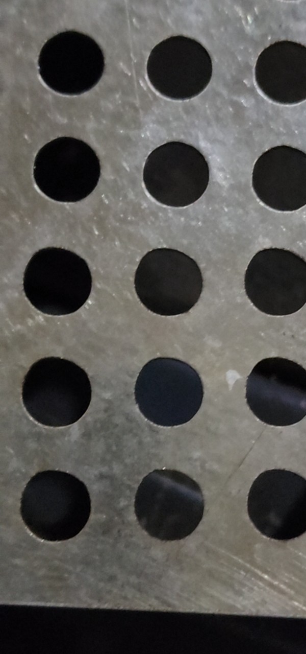
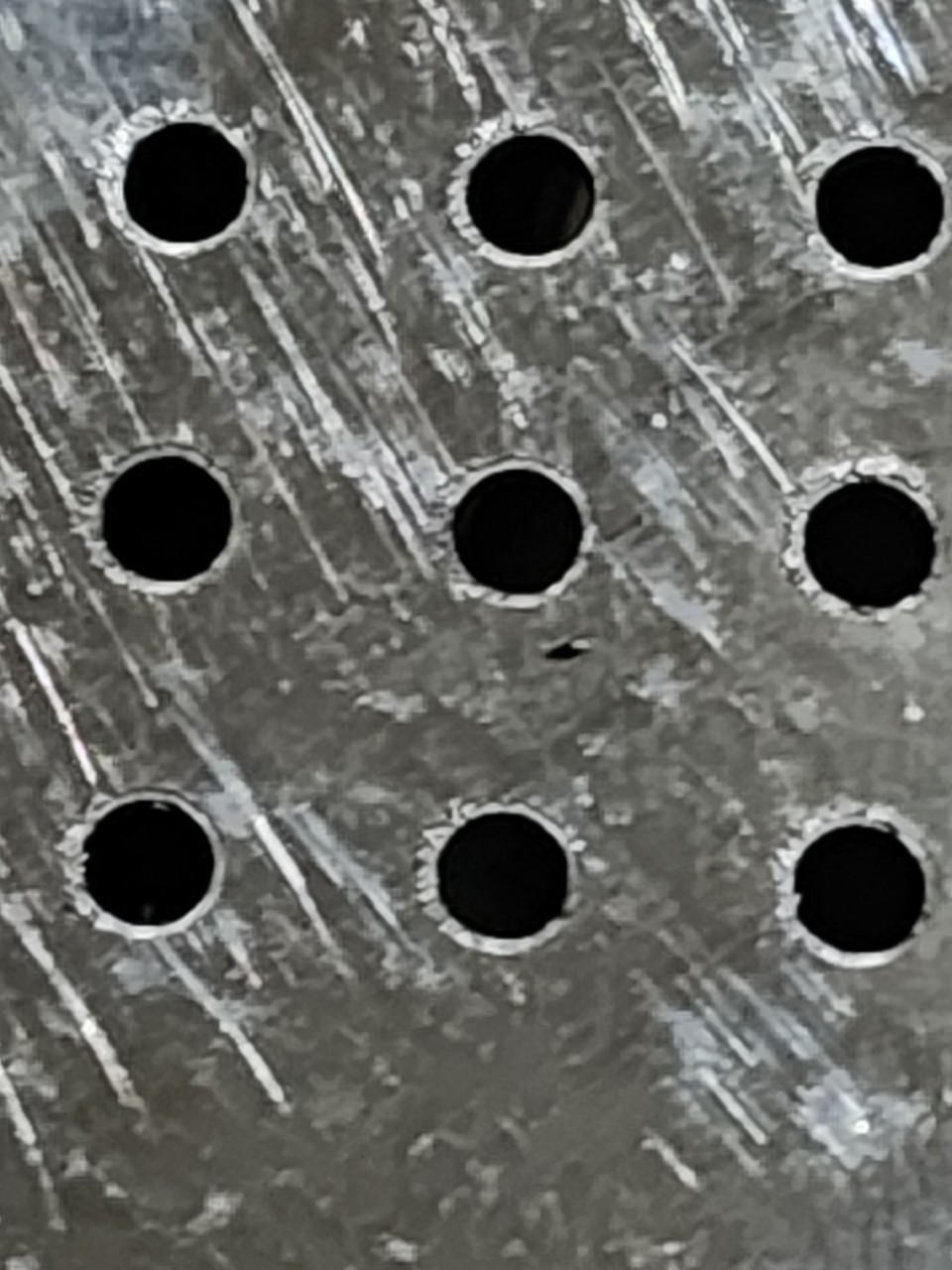
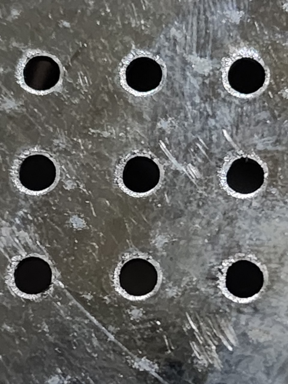
Measure the path-following error
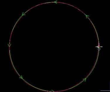
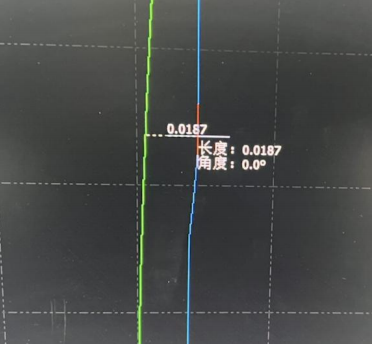
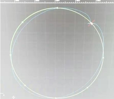
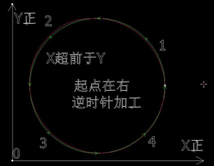
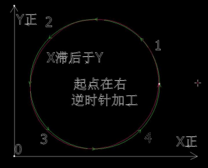
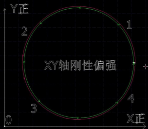
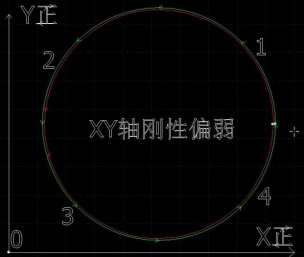
Create a blank program, draw a 5 mm circle and use the controller software’s NC-Error Measurement tool. The machine will move during this measurement. The display compares the commanded path with encoder feedback. The source describes green as the original path and red or blue as the feedback path; a deviation within two wire units (0.02 mm) is treated as acceptable in that procedure. A short dashed segment at the start may be a normal sampling artifact.
Case A: deviation is within 0.02 mm
If the whole measurement is round and deviation is below two wire units, but the cut hole is not round, compare a marking test with a cutting test. Keep the original cutting speed and adjust process parameters only as allowed by the machine maker so the mark is thin and clear.
- If the mark is round but the cut is not, the sheet may be moving under cutting-gas force or may not be supported steadily. Reposition it on the serrated support bars. For thin sheet, the source suggests using the height controller’s vibration-suppression function.
- If the marking circle is not round, reduce the marking speed to 0.5 m/min and repeat the approved test.
- If the mark becomes round at the lower speed, the source points to insufficient mechanical stiffness at higher speed. A qualified technician should inspect the drive train, Z-axis support and X/Y couplings for looseness or deflection.
- If the mark remains out of round at low speed, inspect the mechanical transmission for excessive backlash, damage or obstruction. A technician may use an indicator gauge and isolate components according to the machine manual.
Case B: deviation exceeds 0.02 mm
The source recommends matching X- and Y-axis servo stiffness before fine adjustment; it cites Panasonic level 17 as a reference for its example. Controller models differ, so do not copy that level unless it is specified for your servo and machine.
- Depending on the error pattern, the source lists four tuning directions: reduce X stiffness or increase Y; reduce Y or increase X; reduce both X and Y; or increase both X and Y.
- Make small, documented changes and repeat the measurement using the servo and machine manufacturers’ procedure. If the result remains poor, contact the servo supplier or machine integrator.
- If feedback error is within the machine’s specified limit but the cut remains out of round, return to the sheet, cutting process and mechanical checks in Case A.
Safety and support
The measurement moves machine axes, and servo adjustments can affect machine behavior. Only trained personnel should run the test or change controller parameters, with the work area clear and the machine maker’s safety procedure in place. Send PK LASER the controller model, a screenshot of the trace and a photo of the cut. Zalo: 0394 552 839; technical support: 0394 542 839.