Match the cutting head to the exact laser system
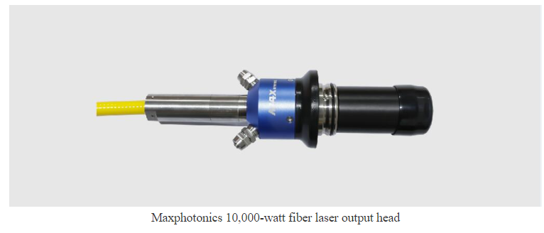
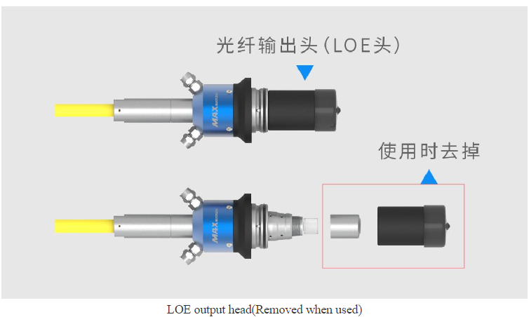
A high-power system requires a cutting head and optical assembly approved for the laser source, wavelength, maximum output and fiber connector. Confirm the interface, collimation and focus optics, adjustment range, sensors and control connections against the manuals for the exact models. A connector or lens ratio mentioned for one system is not automatically suitable for another.
- Confirm written compatibility with the laser-source and cutting-head manufacturers.
- Use the specified protective windows, seals, nozzle and fiber interface.
- Do not exceed the ratings of the head, optics, cable or other components.
Keep optical installation work controlled
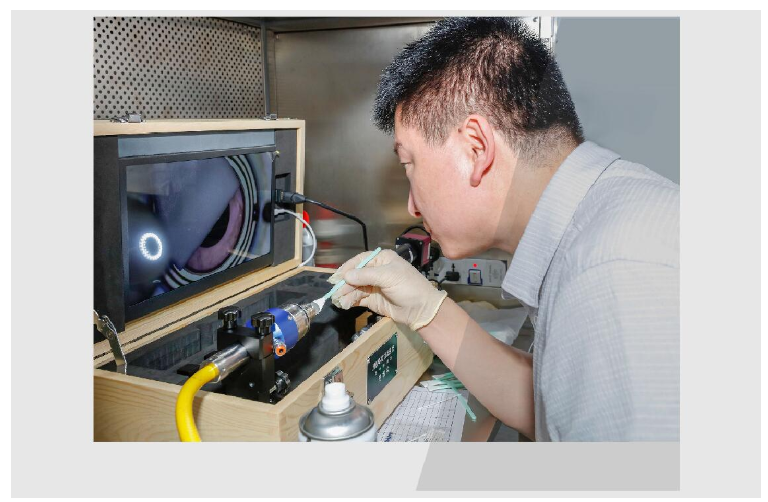
Dust or oil on an optical surface can cause heating and damage. Installation and internal inspection should be done only by personnel trained for that head, using the clean conditions and tools required by its manufacturer. Do not open the fiber output or optical assembly, touch a crystal or lens, or apply a solvent based on a generic guide.
Install and commission by the model manual
Before assembly, isolate the machine and follow laser safety procedures. Check that the specified parts and seals are present and clean, then connect and secure the fiber, head, gas and electrical interfaces exactly as documented. Use the approved procedure for alignment, focus and height calibration. If any interface, seal or optical surface is uncertain, stop and contact qualified service personnel.
Validate the process before production
Check the machine’s axis and height-control functions, focus calibration, nozzle condition, assist-gas supply and safety interlocks using the commissioning checklist. Make controlled test cuts on the intended materials and thicknesses, and confirm both cut quality and repeatability. Do not inspect a high-power beam directly or use an improvised target or viewing method.
Size the cooling system from the equipment specifications
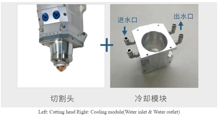
The cutting head and laser source may have separate cooling circuits and different coolant, flow, pressure and temperature requirements. Select and set up the chiller, hose size, connections and flow direction using the manuals for the exact source and head. Values such as flow rate or inlet temperature are model-specific and must not be copied from another 10 kW installation.
Maintenance and abnormal conditions
Inspect accessible protective windows and consumables on the schedule and by the method specified by the manufacturer. Internal optics, fiber connectors and alignment should be handled only by qualified personnel. If a protective window shows a persistent mark, the head overheats, cooling alarms appear, or cut quality changes suddenly, stop the process and arrange a proper inspection before continuing.
Photo suggestion
Use a real installation photo showing the laser-source model, cutting-head model, chiller identification and the labels on the cooling connections. Do not show an open beam path or an optic being handled outside its approved clean environment.