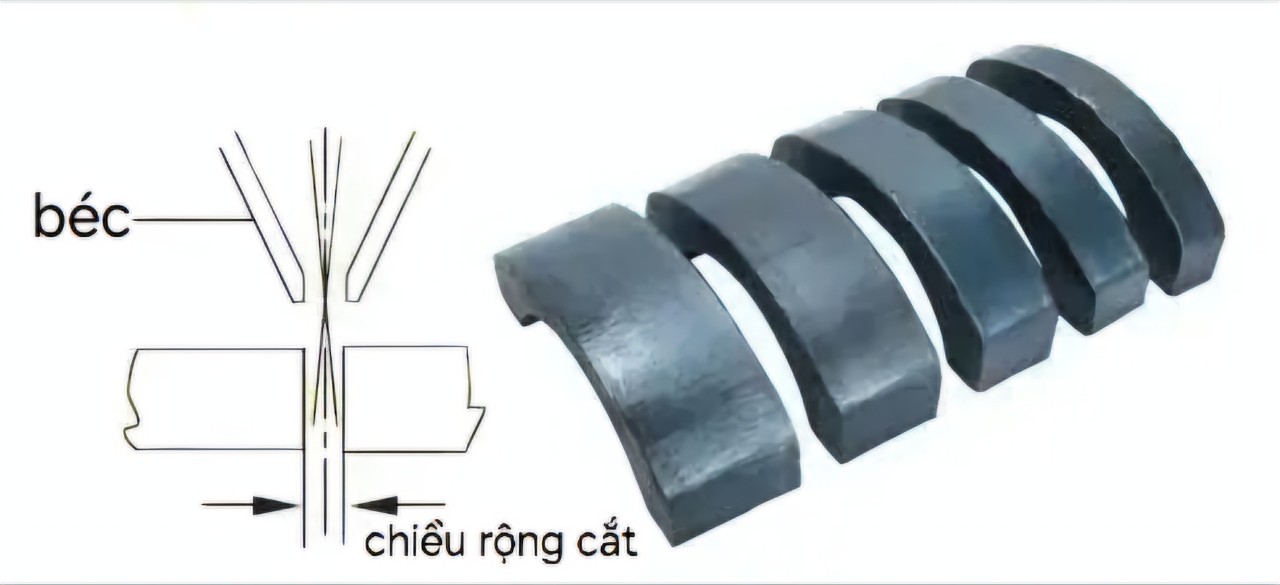
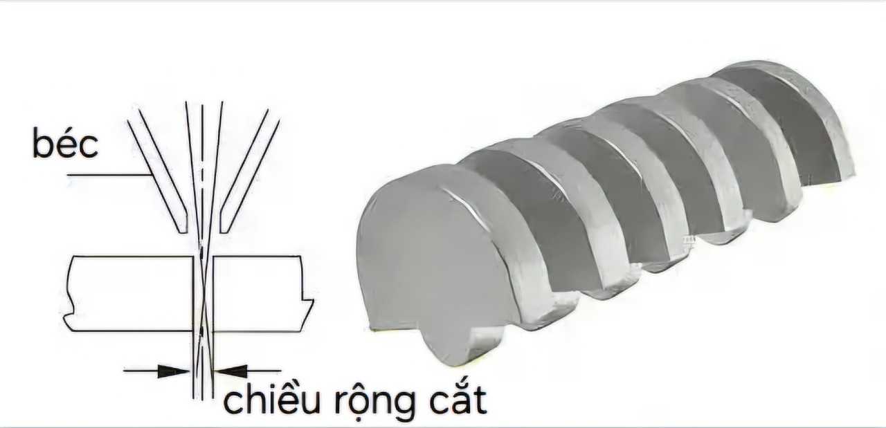
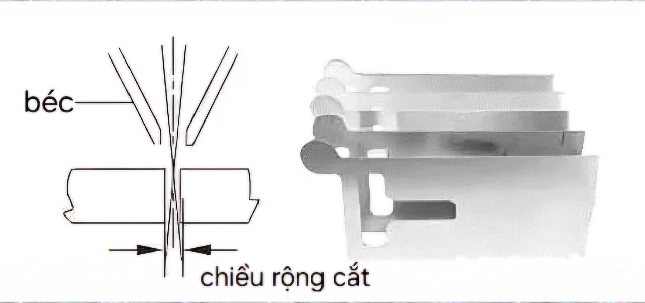
Focus is referenced to the workpiece surface
Focus position describes where the focused beam lies relative to the sheet. Moving the focus can change the beam profile through the material, kerf shape and assist-gas flow. The machine’s sign convention and calibration determine what “positive,” “negative” or “zero” means.
Positive, negative and zero focus are not universal recipes
A focus setting that works for one cutting method, head or material may not work for another. Some process charts specify a focus above the surface, below it or at a reference position. Follow the exact chart for the source, head, material, thickness and assist gas; do not choose focus by the material name alone.
Choose focus from the process requirements
Review the required cut-through, taper, edge finish, dross and production stability. Start from the approved recipe, then make a controlled test cut if adjustment is allowed. Change one permitted value at a time, compare repeatable samples and record the machine’s reference and offset.
Inspect optics and alignment safely
Dirty or damaged optics, nozzle defects and beam misalignment can affect focus and cut quality. Stop the machine and follow the head maker’s inspection procedure. Do not use improvised black-paper, tape or open-beam tests, or run a high-power test to heat a nozzle. Have optical alignment and high-power checks done by qualified personnel using approved equipment.
Photo suggestion
Show labeled test coupons for the approved focus settings on the same material and thickness, with the head model and cut result recorded. Use diagrams to explain the sign convention for that machine.